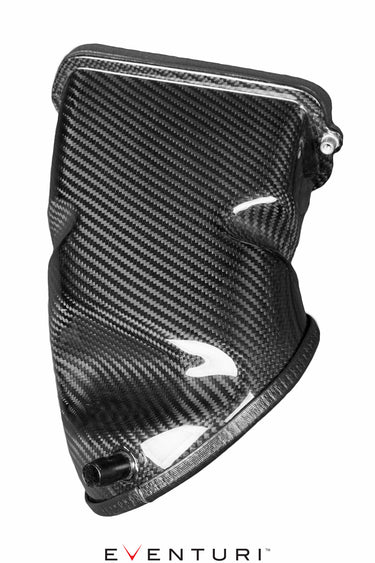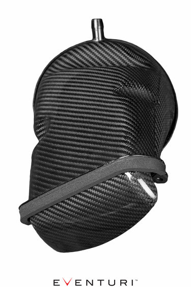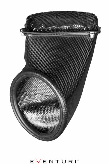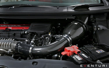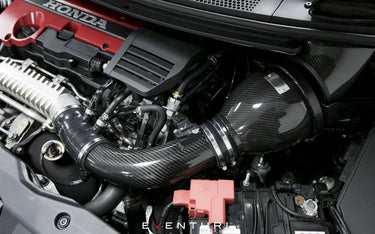

This is a step-by-step guide to installing the Eventuri V2 Intake System to show you everything you need to be up and running. Begin by gathering all the necessary tools before starting the installation process.
Tools required for installation:
10mm Socket | Philips Head Screw Driver | Trim Removal Tools | Torx Head Allen Key | Pliers
If you require further assistance installing this product please get it in contact.
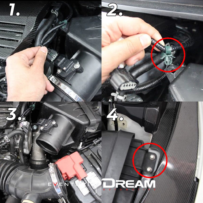
Part 1-4
1. Unplug the MAF sensor plug as shown.
2. Remove the sensor wiring harness from the airbox – push the green tabs inwards to allow you to pull the clip out.
3. Loosen and remove the rubber intake hose from the airbox.
4. Remove the 2 10mm bolts from the intake duct.
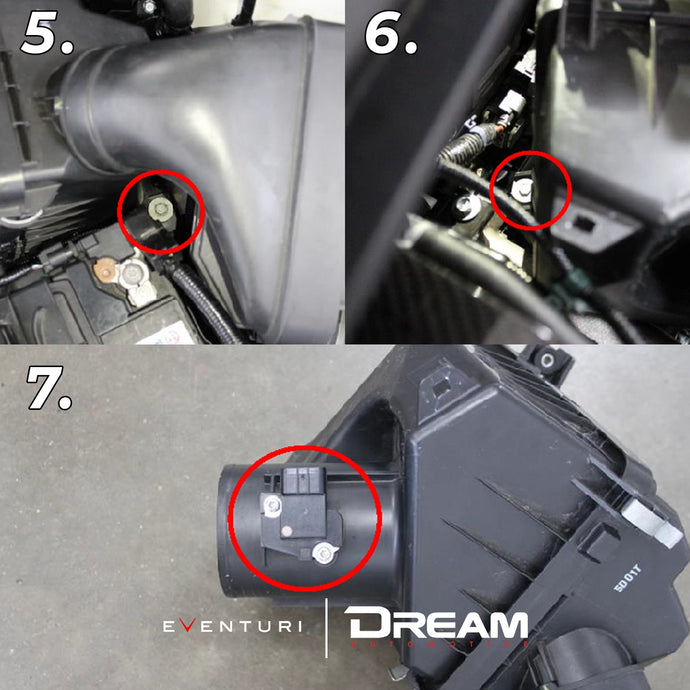
Part 5-7
5. The Airbox is held in with 2 10mm bolts. Remove the front one as shown behind
the battery.
6. Remove the remaining bolt which is located at the back of the airbox. Now pull the entire airbox assembly out.
7. Remove the MAF sensor by unscrewing the 2 screws holding it to the airbox.
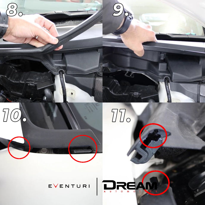
Part 8-11
8. Pull rubber trim off the left side plastic panels in front of the windscreen. The left one as you look at the engine.
9. Pull the plastic panel upwards to unclip it.
10. Unclip the 2 tabs holding the panel into the wing. Push the panel down to unclip them.
11. Now pull the panel down to unclip from the windscreen panel. There is a long tab which locates into the hole in the panel as shown. Remove panel completely
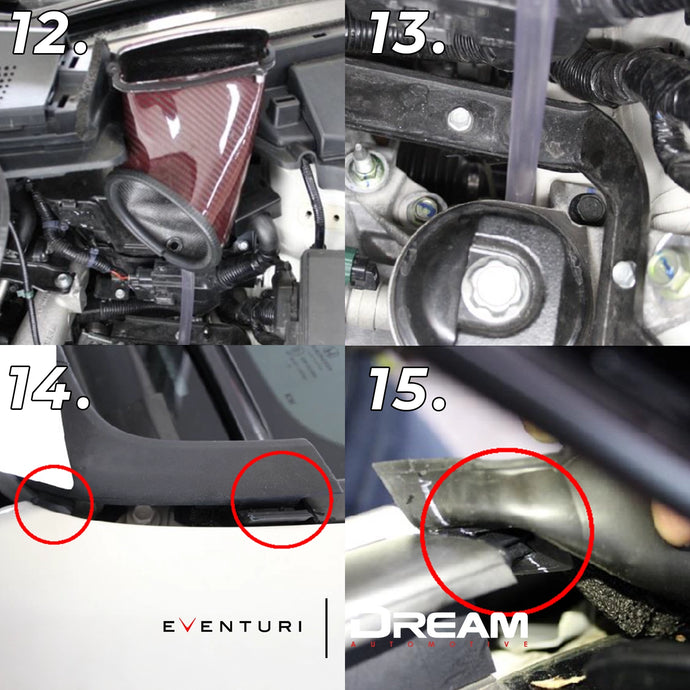
Part 12-15
12. Place the carbon duct into the space revealed under the removed plastic cover. This will be secured in the coming steps.
13. Position the drain tube as shown.
14. Now take the supplied plastic panel which has been pre-cut and install by firstly clicking the side tabs into place. 15. Now push the locating tab from the windscreen panel into the hole of this new panel as shown.
15. Now push the locating tab from the windscreen panel into the hole of this new panel as shown.
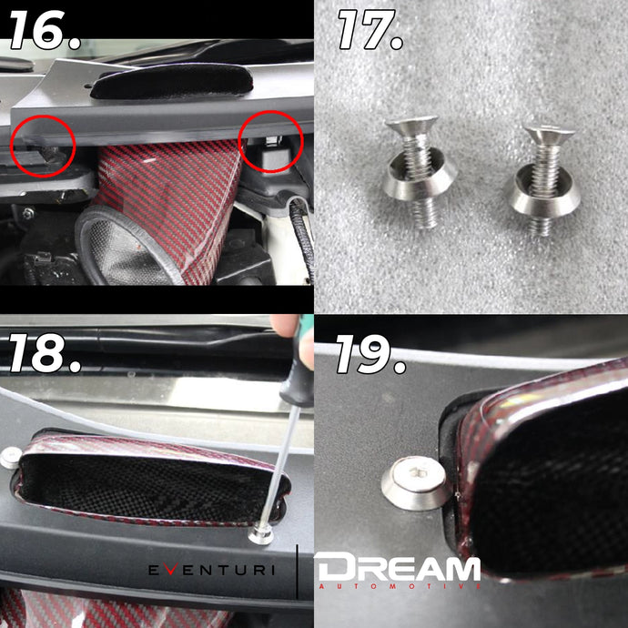
Part 16-19
16. Now click all the tabs into place – make sure they go into the correct positions. There are tabs at the back too. Push the panel down all around to click into place.
17. We will use the supplied countersunk screws and washers to secure the duct to the plastic panel.
18. Position the duct to line up the threaded inserts with the holes on the panel and secure with the supplied screws. Do not over tighten them.
19. Be careful with the left side screw, push the washer away from the duct as you tighten to avoid scratching the carbon. .
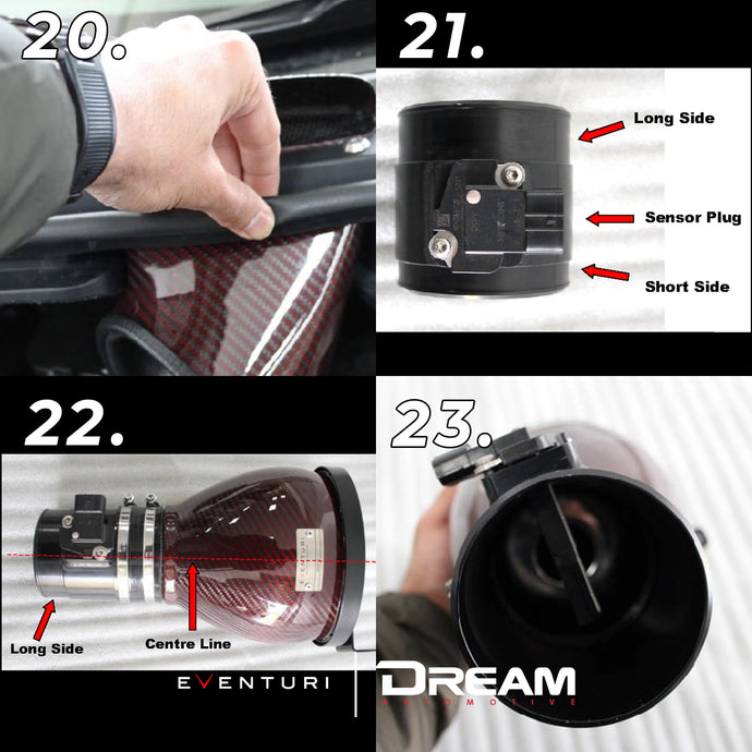
Part 20-23
20. Push the rubber trim back into place.
21. Install the MAF sensor onto the supplied sensor tube as shown with correct orientation. Secure with the two supplied M4 screws.
22. Assemble the tube to the carbon filter housing with the supplied silicon hose as shown. The short side of the MAF tube should be inserted into the silicon. This leaves the long side exposed. The sensor should also be oriented slightly off-centre as shown here and in the next step.
23. Orientation of the MAF sensor with the metal badge on the housing facing upwards.
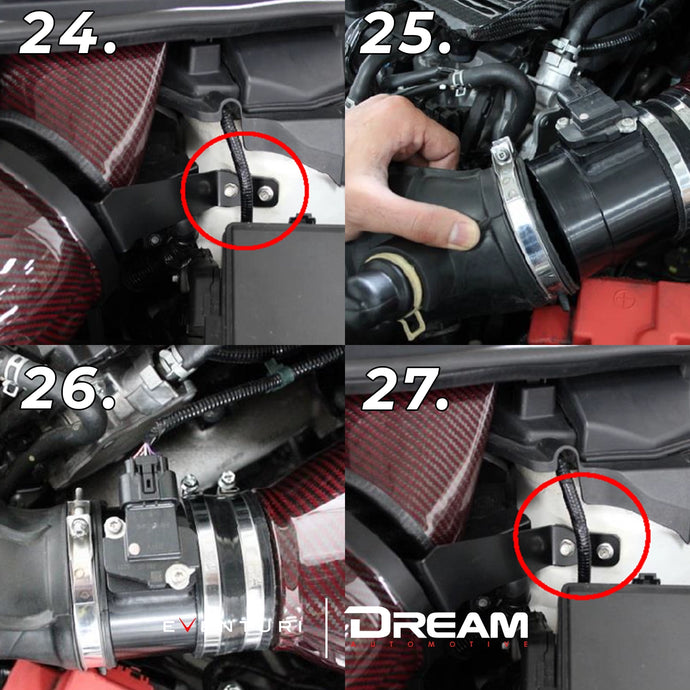
Part 24-27
24. Position the bracket which is attached to the housing over the 2 threaded holes on the arch DO NOT secure with the supplied bolts yet.
25. Push the stock rubber hose onto the MAF tube – make sure the clamp is loose. Support the housing while pushing the hose on.
26. Tighten the hose clamp around the rubber tube. Click the MAF sensor plug into place. If the MAF sensor wire is tight, loosen the hose clamps around the silicon coupler and rotate the MAF tube further to give the wire slack.
27. Now secure the intake using the 2 supplied M6 bolts.
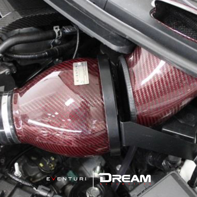
Part 28
28. The assembly should look like this – there will be a gap between the intake housing and the duct. This is required so as not to restrict airflow to the filter. It will still be saturated with cold air from the duct.
Ensure all hose clamps are tight and the MAF plug is connected properly.
Eventuri and Dream Automotive cannot take responsibility for an incorrectly installed intake or any damage caused during installation.